Dynomotion

Group: DynoMotion Message: 11382 From: psorey@rocketmail.com Date: 4/14/2015
Subject: 3D printing in Spherical Space with KFLOP - basic questions

Current Plan and Questions:

Machine Basic Description:

Our 3-D printer (fabrication nearly complete) has circular rails, 1) full 360-degree track in the X-Y plane for rotation around the Z-axis. 2) on that track, standing up vertically at 90 degrees to the circular track, rotates a half-circle arch gantry, and, 3) along that gantry travels a tool carriage holding a linear actuator with the printing nozzle that points towards the center of the hemisphere circumscribed by the arcs.

Inside the spherical space circumscribed by the rails of the machine, is a smaller diameter, roughly hemispherical form (with some protrusions) that we are going to spray onto.

The machine uses 3 axes to coordinate arrival at xyz, and then has a knuckle, (either 1 or 2 axes, we're not sure yet) to point the spray sideways and perhaps up and down.  Two of the three axes are driven by 1500W servos with H2N-TD AC Servo Drivers, the arch gantry is driven by two, one at the base of each end.  The plan is to mark each quadrant of the circle with magnets, and if a mismatch is detected (I.e, if the two ends do not show as exactly 180 degrees apart, a PID routine will bring them back into alignment. Not sure where this PID routine will happen.

Questions: 
1.   I assume we need 2 separate streams of Gcode, what is the basic method for this?
2.   Can one KFLOP board handle a 5-axis system, or do we need two?  (sorry for basic questions).
3.    We will not use the board stand-alone, but will want to stream Gcode in real time, based on information gathered while traversing the path.  Where is a FIFO  buffer  that we can stream the Gcode into for processing by KFLOP? Or does that need to happen in software outside the KFLOP board? 


We plan to perform spherical to xyz conversion in Kmotion, kinetics_spherical.cpp, subclassed from Kinetics class so we can have xyz Gcode, and can read xyz coordinates from the Kmotion display.  Could use help with this.

Questions:
1.   Our machine's x-axis is circular, and infinite.  We will go around and around the hemisphere working our way from bottom to top.  Kinetics_xxx.cpp needs to know axis lengths, so how do I handle this?
2.   When generating Gcode we would like to simply use a series of 3D points along our path. How will KFlop know to keep going forward when we have made one revolution? 
3.   I believe Rhino/RhinoCam  or Rhino/VisualMill can plan our 5-axis paths, is that correct?

Many more questions, but this will help me get going. We are near Eugene, OR.    

Thank you.


  @@attachment@@
Group: DynoMotion Message: 11384 From: karmannelectric Date: 4/14/2015
Subject: Re: 3D printing in Spherical Space with KFLOP - basic questions
Paul,
This might be the most weird/interesting CNC application I've ever
seen... can you provide more details on what the heck it is you are
trying to do?

- Steve

> Hi Paul,
> Regarding:
> #1 - I don't see the need for two streams of GCode.  Can you explain
> this?#2 - One KFLOP should work.  It allows up to 6 axes of coordinated
> motion plus up to 2 additional slaved ore independent axes.#3 - Our GCode
> interpreter runs on the PC is not really set up for streaming.  It
> executes a file.  I suppose you could keep creating and submitting
> smaller files as "blocks" or something.  Below our GCode Interpreter
> layer is our Coodinated Motion Libraries where you can submit motion
> segment by segment or arc by arc from your application.  That might be
> another approach.
> Regarding kinematics:  Have you worked out the geometrical equations? 
> I think you will need to work out how to compute the actuator positions
> given an xyz location.  Seems relatively straightforward involving a
> center point Xc, Yc, Zc and the xyz target CAD point and computing some
> deltas and some arc-tangents.   The reverse transformation should be
> handled automatically by the Kinematics class using a general numerical
> method.
> Regarding going around and around.  I think you can handle that in the
> Kinematics.  When computing the arc-tangent adjust the result by however
> many 2 Pi to as close as possible to the last angle.  See the attached
> Tangential Knife algorithm attached.  How many revs do you expect to
> go?  I suppose there might be some numerical issues if it is over
> thousands.
> I don't know how you would plan the 5 axis paths.
> RegardsTK
>
> From: "paul@... [DynoMotion]" <DynoMotion@yahoogroups.com>
> To: DynoMotion@yahoogroups.com
> Sent: Tuesday, April 14, 2015 2:42 PM
> Subject: [DynoMotion] 3D printing in Spherical Space with KFLOP - basic
> questions [1 Attachment]
>
>   [Attachment(s) from paul@... [DynoMotion] included below]
> Current Plan and Questions:
>
> Machine Basic Description:
>
> Our 3-D printer (fabrication nearly complete) has circular rails, 1) full
> 360-degree track in the X-Y plane for rotation around the Z-axis. 2) on
> that track, standing up vertically at 90 degrees to the circular track,
> rotates a half-circle arch gantry, and, 3) along that gantry travels a
> tool carriage holding a linear actuator with the printing nozzle that
> points towards the center of the hemisphere circumscribed by the arcs.
>
> Inside the spherical space circumscribed by the rails of the machine, is a
> smaller diameter, roughly hemispherical form (with some protrusions) that
> we are going to spray onto.
>
> The machine uses 3 axes to coordinate arrival at xyz, and then has a
> knuckle, (either 1 or 2 axes, we're not sure yet) to point the spray
> sideways and perhaps up and down.  Two of the three axes are driven by
> 1500W servos with H2N-TD AC Servo Drivers, the arch gantry is driven by
> two, one at the base of each end.  The plan is to mark each quadrant of
> the circle with magnets, and if a mismatch is detected (I.e, if the two
> ends do not show as exactly 180 degrees apart, a PID routine will bring
> them back into alignment. Not sure where this PID routine will happen.
>
> Questions: 
> 1.   I assume we need 2 separate streams of Gcode, what is the basic
> method for this?
> 2.   Can one KFLOP board handle a 5-axis system, or do we need two? 
> (sorry for basic questions).
> 3.    We will not use the board stand-alone, but will want to stream
> Gcode in real time, based on information gathered while traversing the
> path.  Where is a FIFO  buffer  that we can stream the Gcode into for
> processing by KFLOP? Or does that need to happen in software outside the
> KFLOP board? 
>
> We plan to perform spherical to xyz conversion in Kmotion,
> kinetics_spherical.cpp, subclassed from Kinetics class so we can have xyz
> Gcode, and can read xyz coordinates from the Kmotion display.  Could use
> help with this.
>
> Questions:
> 1.   Our machine's x-axis is circular, and infinite.  We will go around
> and around the hemisphere working our way from bottom to top. 
> Kinetics_xxx.cpp needs to know axis lengths, so how do I handle this?
> 2.   When generating Gcode we would like to simply use a series of 3D
> points along our path. How will KFlop know to keep going forward when we
> have made one revolution? 
> 3.   I believe Rhino/RhinoCam  or Rhino/VisualMill can plan our 5-axis
> paths, is that correct?
>
> Many more questions, but this will help me get going. We are near Eugene,
> OR.    
>
> Thank you.
>
> #yiv7579908765 #yiv7579908765 -- #yiv7579908765ygrp-mkp {border:1px
> solid #d8d8d8;font-family:Arial;margin:10px 0;padding:0
> 10px;}#yiv7579908765 #yiv7579908765ygrp-mkp hr {border:1px solid
> #d8d8d8;}#yiv7579908765 #yiv7579908765ygrp-mkp #yiv7579908765hd
> {color:#628c2a;font-size:85%;font-weight:700;line-height:122%;margin:10px
> 0;}#yiv7579908765 #yiv7579908765ygrp-mkp #yiv7579908765ads
> {margin-bottom:10px;}#yiv7579908765 #yiv7579908765ygrp-mkp
> .yiv7579908765ad {padding:0 0;}#yiv7579908765 #yiv7579908765ygrp-mkp
> .yiv7579908765ad p {margin:0;}#yiv7579908765 #yiv7579908765ygrp-mkp
> .yiv7579908765ad a {color:#0000ff;text-decoration:none;}#yiv7579908765
> #yiv7579908765ygrp-sponsor #yiv7579908765ygrp-lc
> {font-family:Arial;}#yiv7579908765 #yiv7579908765ygrp-sponsor
> #yiv7579908765ygrp-lc #yiv7579908765hd {margin:10px
> 0px;font-weight:700;font-size:78%;line-height:122%;}#yiv7579908765
> #yiv7579908765ygrp-sponsor #yiv7579908765ygrp-lc .yiv7579908765ad
> {margin-bottom:10px;padding:0 0;}#yiv7579908765 #yiv7579908765actions
> {font-family:Verdana;font-size:11px;padding:10px 0;}#yiv7579908765
> #yiv7579908765activity
> {background-color:#e0ecee;float:left;font-family:Verdana;font-size:10px;padding:10px;}#yiv7579908765
> #yiv7579908765activity span {font-weight:700;}#yiv7579908765
> #yiv7579908765activity span:first-child
> {text-transform:uppercase;}#yiv7579908765 #yiv7579908765activity span a
> {color:#5085b6;text-decoration:none;}#yiv7579908765
> #yiv7579908765activity span span {color:#ff7900;}#yiv7579908765
> #yiv7579908765activity span .yiv7579908765underline
> {text-decoration:underline;}#yiv7579908765 .yiv7579908765attach
> {clear:both;display:table;font-family:Arial;font-size:12px;padding:10px
> 0;width:400px;}#yiv7579908765 .yiv7579908765attach div a
> {text-decoration:none;}#yiv7579908765 .yiv7579908765attach img
> {border:none;padding-right:5px;}#yiv7579908765 .yiv7579908765attach
> label {display:block;margin-bottom:5px;}#yiv7579908765
> .yiv7579908765attach label a {text-decoration:none;}#yiv7579908765
> blockquote {margin:0 0 0 4px;}#yiv7579908765 .yiv7579908765bold
> {font-family:Arial;font-size:13px;font-weight:700;}#yiv7579908765
> .yiv7579908765bold a {text-decoration:none;}#yiv7579908765
> dd.yiv7579908765last p a
> {font-family:Verdana;font-weight:700;}#yiv7579908765
> dd.yiv7579908765last p span
> {margin-right:10px;font-family:Verdana;font-weight:700;}#yiv7579908765
> dd.yiv7579908765last p span.yiv7579908765yshortcuts
> {margin-right:0;}#yiv7579908765 div.yiv7579908765attach-table div div a
> {text-decoration:none;}#yiv7579908765 div.yiv7579908765attach-table
> {width:400px;}#yiv7579908765 div.yiv7579908765file-title a,
> #yiv7579908765 div.yiv7579908765file-title a:active, #yiv7579908765
> div.yiv7579908765file-title a:hover, #yiv7579908765
> div.yiv7579908765file-title a:visited
> {text-decoration:none;}#yiv7579908765 div.yiv7579908765photo-title a,
> #yiv7579908765 div.yiv7579908765photo-title a:active, #yiv7579908765
> div.yiv7579908765photo-title a:hover, #yiv7579908765
> div.yiv7579908765photo-title a:visited
> {text-decoration:none;}#yiv7579908765 div#yiv7579908765ygrp-mlmsg
> #yiv7579908765ygrp-msg p a span.yiv7579908765yshortcuts
> {font-family:Verdana;font-size:10px;font-weight:normal;}#yiv7579908765
> .yiv7579908765green {color:#628c2a;}#yiv7579908765
> .yiv7579908765MsoNormal {margin:0 0 0 0;}#yiv7579908765 o
> {font-size:0;}#yiv7579908765 #yiv7579908765photos div
> {float:left;width:72px;}#yiv7579908765 #yiv7579908765photos div div
> {border:1px solid
> #666666;height:62px;overflow:hidden;width:62px;}#yiv7579908765
> #yiv7579908765photos div label
> {color:#666666;font-size:10px;overflow:hidden;text-align:center;white-space:nowrap;width:64px;}#yiv7579908765
> #yiv7579908765reco-category {font-size:77%;}#yiv7579908765
> #yiv7579908765reco-desc {font-size:77%;}#yiv7579908765
> .yiv7579908765replbq {margin:4px;}#yiv7579908765
> #yiv7579908765ygrp-actbar div a:first-child
> {margin-right:2px;padding-right:5px;}#yiv7579908765
> #yiv7579908765ygrp-mlmsg {font-size:13px;font-family:Arial, helvetica,
> clean, sans-serif;}#yiv7579908765 #yiv7579908765ygrp-mlmsg table
> {font-size:inherit;font:100%;}#yiv7579908765 #yiv7579908765ygrp-mlmsg
> select, #yiv7579908765 input, #yiv7579908765 textarea {font:99% Arial,
> Helvetica, clean, sans-serif;}#yiv7579908765 #yiv7579908765ygrp-mlmsg
> pre, #yiv7579908765 code {font:115% monospace;}#yiv7579908765
> #yiv7579908765ygrp-mlmsg * {line-height:1.22em;}#yiv7579908765
> #yiv7579908765ygrp-mlmsg #yiv7579908765logo
> {padding-bottom:10px;}#yiv7579908765 #yiv7579908765ygrp-msg p a
> {font-family:Verdana;}#yiv7579908765 #yiv7579908765ygrp-msg
> p#yiv7579908765attach-count span
> {color:#1E66AE;font-weight:700;}#yiv7579908765 #yiv7579908765ygrp-reco
> #yiv7579908765reco-head {color:#ff7900;font-weight:700;}#yiv7579908765
> #yiv7579908765ygrp-reco {margin-bottom:20px;padding:0px;}#yiv7579908765
> #yiv7579908765ygrp-sponsor #yiv7579908765ov li a
> {font-size:130%;text-decoration:none;}#yiv7579908765
> #yiv7579908765ygrp-sponsor #yiv7579908765ov li
> {font-size:77%;list-style-type:square;padding:6px 0;}#yiv7579908765
> #yiv7579908765ygrp-sponsor #yiv7579908765ov ul {margin:0;padding:0 0 0
> 8px;}#yiv7579908765 #yiv7579908765ygrp-text
> {font-family:Georgia;}#yiv7579908765 #yiv7579908765ygrp-text p {margin:0
> 0 1em 0;}#yiv7579908765 #yiv7579908765ygrp-text tt
> {font-size:120%;}#yiv7579908765 #yiv7579908765ygrp-vital ul
> li:last-child {border-right:none !important;}#yiv7579908765
>
>
Group: DynoMotion Message: 11386 From: Tom Kerekes Date: 4/14/2015
Subject: Re: 3D printing in Spherical Space with KFLOP - basic questions
Hi Paul,

It seems to me what you describe is simply a single 5 Axis GCode sequence using XYZAB for the Axis.  It would all be coordinated motion.  In some cases only XYZ might be changing, in others only AB, or in others all XYZAB might be changing.  The overall path would consist of a sequence of 5 dimensional points or basically short line segments. 

You will also need to decide how to specify the feed rate.  Normally if X, Y, or Z are changing then they and only they determine the feed rate.  A and B will move at whatever rate to "keep up".  In the case where neither X, Y, or Z move then the Feed rate specifies the Angular rate of A and B.  An alternate approach is to explicitly specify the time between each 5 axes point.  This is called inverse Time mode because the reciprocal of the time is actually what is specified in the GCode (I think this is due to historical reasons when processors were very slow at division and this helped speed up the calculations)

HTH
Regards
TK 

Group: DynoMotion Message: 11387 From: Hardy Family Date: 4/14/2015
Subject: Re: 3D printing in Spherical Space with KFLOP - basic questions
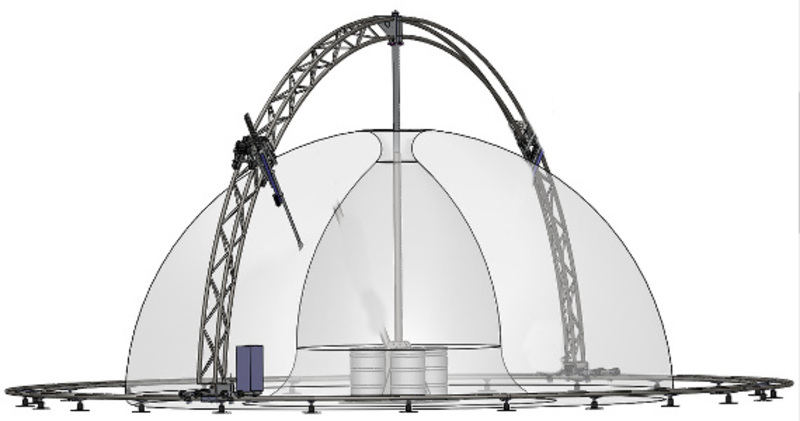
Interesting machine, I must say.

Regarding the "PID" correction of the master/slave azimuth axis:  I take it that your drive system allows some slippage, like maybe it is a friction drive not a circular rack.  So you need to correct for relative displacement between the two driving sides.  You can only perform the correction at the quadrant points where there is some sort of index pulse.  Is this roughly correct?

If so, then one way I would try would be to have a dedicated thread running in the kflop, which looks for the index pulses encountered by master and slave (M,S).  Initially, your slave gain would be 1 (i.e. exactly 1:1 ratio of M to S).  Since you said it basically moves in one direction, then you should be able to assume that there has been roughly 90 degrees of motion between each index pulse received.  When 2 index pulses have been seen from both M and S, then you can compute whether S is running fast or slow w.r.t. M.  Using that data, you re-compute the slave gain to compensate.

This is made a bit tricky because:
- you need to catch up ("anti racking") over some interval, then revert to the theoretical adjusted gain thereafter (unless you can tolerate a discontinuity where you pause and move the slave axis to 180 deg opposite the master).  Maybe it would be sufficient to adjust the slave gain by an additional amount depending on the angular offset, which will make it catch up over a longer period, but should still converge on the correct gain and offset, like a PLL.
- When you change the slave gain, I am not sure whether the kflop will "jump" the slave, or whether it adjusts the ratio with no positional discontinuity.  Tom would have to answer this.
- You probably want the master axis to maintain an absolute reference w.r.t one of the index pulses, so you will want to adjust its output gain as well.

Regarding the "streaming" (dynamic generation) of g-code: as Tom noted, it's really file oriented, because it sometimes needs to seek around in the file to locate subroutines etc.  Maybe g-code is not a very good fit for your application because of its extremely limited decision/feedback capability.  You can fake it to some extent by having the kflop issue MDI commands to the PC.  I guess it depends on what sensors/events drive the dynamics, and whether the sensors are available to the kflop or the PC.  You seem to have more of a robot type machine than a "dumb" CNC device.

Of all the great things about the kflop, one that stands out is the ability to move away from the g-code model, and move more towards a robotics model i.e. more feedback.  For example, on our machine we now have dynamic force feedback, simply by monitoring the integrator windup and following error on each axis.

Regards,
SJH


On Tue, Apr 14, 2015 at 10:22 PM, Tom Kerekes tk@... [DynoMotion] <DynoMotion@yahoogroups.com> wrote:
 

Hi Paul,

It seems to me what you describe is simply a single 5 Axis GCode sequence using XYZAB for the Axis.  It would all be coordinated motion.  In some cases only XYZ might be changing, in others only AB, or in others all XYZAB might be changing.  The overall path would consist of a sequence of 5 dimensional points or basically short line segments. 

You will also need to decide how to specify the feed rate.  Normally if X, Y, or Z are changing then they and only they determine the feed rate.  A and B will move at whatever rate to "keep up".  In the case where neither X, Y, or Z move then the Feed rate specifies the Angular rate of A and B.  An alternate approach is to explicitly specify the time between each 5 axes point.  This is called inverse Time mode because the reciprocal of the time is actually what is specified in the GCode (I think this is due to historical reasons when processors were very slow at division and this helped speed up the calculations)

HTH
Regards
TK 

Group: DynoMotion Message: 11406 From: psorey@rocketmail.com Date: 4/15/2015
Subject: Re: 3D printing in Spherical Space with KFLOP - basic questions
Wow, SJH, very helpful response and I'm digesting it one bite at a time!  Thank you.
Regards,
Paul
Group: DynoMotion Message: 11444 From: geraldft Date: 4/28/2015
Subject: Re: 3D printing in Spherical Space with KFLOP - basic questions
Hi Paul

It does sound a bit like some inverse kinematics for the spray device would be useful.  You might simplify the whole process by building an IK of the nozzle device complete with wrist etc.  Then define the path for the spray and the direction of the spray.  Combine the two and you have a basis to work with. 

Gerald
Group: DynoMotion Message: 11447 From: psorey@rocketmail.com Date: 4/30/2015
Subject: Re: 3D printing in Spherical Space with KFLOP - basic questions
I think you're right, Gerald.  Working on it. I'll let you know how it goes.

Thanks,

Paul